
Strut Test - Determination of Euler's Buckling Load
The buckling load of a strut is defined as the load at which the strut buckles, under the action of an external load. It is also called a critical load or crippling load.
A buckling load test on the strut is conducted to evaluate the effect of specimen length on the buckling of the strut, and the failure load with the theoretical failure loads obtained using Euler's equation for column/strut buckling.

Note: Columns and struts are axial compression members. Columns are short and vertical, while struts are more slender compared to columns. A slender thin rod is more likely to buckle compared to a stout rod.
Euler's Buckling Load Strut
Buckling occurs when the compressive stress of the member is within the range of linear elasticity or less than the yield stress. This happens suddenly without warning and could cause dangerous failures. Hence, buckling is an elastic stability problem.
There is a critical load limit above which buckling can occur, which is dependent on the slenderness (kL/r) of the rod and the type of material of the strut. This load is called Euler's load.
Euler's Formula for Column Buckling Load
The theoretical equation to determine Euler's buckling load is given are:

Pcr = Euler's buckling load
E = Modulus of elasticity
A = Area of a cross-section of the strut
K = effective length factor
L= Length of strut
Le = Effective length = KL
r= radius of gyration = sqrt (I/A)
I = Moment of inertia
The effective length factor is dependent on the constraints imposed on the ends of the column. The below figure shows how effective length Le is related to the actual length of the struts.
 |
| Effective Length Le related to the Actual Length L for Different End Conditions of Columns |
Laboratory Test for Buckling Load of Struts
Equipment Required
1. Strut Column Buckling Apparatus
This equipment is used to find the loss of elastic stability i.e. buckling of a sample strut. In this apparatus, the bar sample is clamped and supported at the ends in the experimental unit based on the end constraints.
 |
| Fig.2. Strut Column Test Equipment with Touch LCD Display |
A height-adjustable loading member is there which can be hand-operated to apply a compressive force to the bar. In order to prevent torsional stress on the test bar, axial support between the spindle and the bar support is provided.
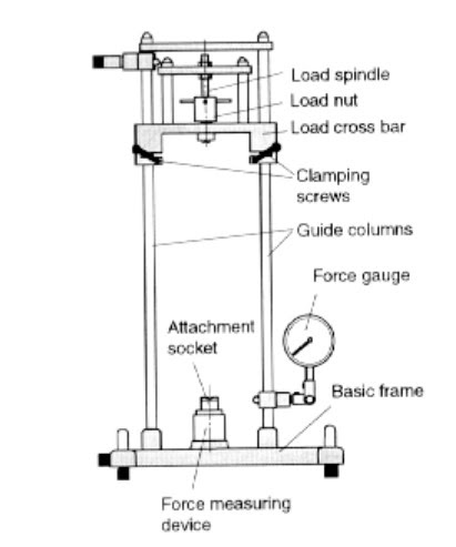 |
| Fig.3. Strut Column Test Equipment with Force Guage |
The above equipment can be used both vertically and horizontally based on the convenience of measurement.
2. Dial Guage or Touch LCD Display
With the loading unit of the equipment, compressive force is applied in intervals and the respective deflection is either measured using a dial gauge or a Touch LCD display. The value increases with increasing load and suddenly and violently decreases which is corresponding to the failure of the strut.
Test Procedure
1. Set up the equipment in vertical or horizontal positions. If a force dial gauge is used, it can be turned 90 degrees based on the position.
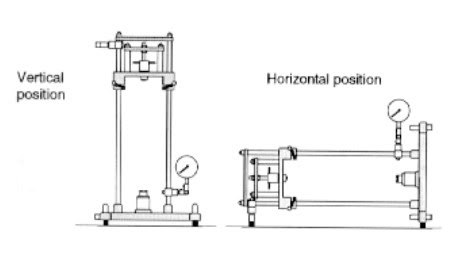 |
| Fig.4. Positioning the Strut buckling test equipment |
2. Zero the load readout by rotating the "Set Zero" knob. Clean the strut using sandpaper. Now insert the rod specimen between the top and bottom adapter.
3. Follow the arrangement for different end conditions required:
- Case 1: Two Ends Pinned-Place the strut member on the V notch on the adapters.
- Case 2: When One End is Pinned and Another End is Fixed-Place the top end of the strut in a V notch and the bottom end is fixed at the bottom.
- Case 3: When Both Ends are Fixed-Fix the strut at the top and bottom.
4. Start to rotate the load assembly until the load is applied to the strut.
5. See the load reading in the force display unit.
6. Load initially increases and finally reaches a constant value. This is the buckling load for the strut.
7. The different strut lengths available for testing will be 520 mm, 470, 420, 370, and 320 mm.
8. Determine the buckling load with the theoretical Euler's buckling load determined for each strut sample for respective end conditions.
- Case 1: Two Ends Pinned Pcr = Π2EI/L2
- Case 2: When One End is Pinned and Another End is Fixed-Place the top end of the strut in a V notch and the bottom end is fixed at the bottom. Pcr = 2Π2EI/L2
- Case 3: When Both Ends are Fixed Pcr = 4Π2EI/L2
Observations and Calculations
|
Strut Number |
Length (mm) |
Buckling Load (N) |
Average Buckling Load (N) |
|||
|
1 |
2 |
3 |
4 |
|||
|
1 |
520 |
|
|
|
|
|
|
2 |
470 |
|
|
|
|
|
|
3 |
420 |
|
|
|
|
|
|
4 |
370 |
|
|
|
|
|
|
5 |
320 |
|
|
|
|
|
Analysis and Results
Plot the graph between 1/L2 and The average buckling load (N). The graph will be a straight line. From the graph for each end condition, the respective Π2EI is determined as the gradient of the line.
From this, the second moment of inertia is calculated and the theoretical Euler's buckling is calculated.
Results
Strut buckling load by Eulers Formula = ------N
Experimental Buckling load of strut = ------N
0 Comments
Commenting Spam Links Are Against Policies