
Working Stress Method (WSM) vs Limit State Method (LSM) in Structural Engineering
Working Stress Method (WSM) and Limit State Method (LSM) are two common methods used in structural engineering for designing and analyzing structures. The Working Stress Method (WSM) is an older method that has been largely replaced by the Limit State Method (LSM) in most parts of the world. vs Limit State Method (LSM) in Structural Engineering")
In this article, we will discuss the basic features and the differences between WSM and LSM design methods with the help of an example.
In contrast, the Limit State Method (LSM) is a more modern and widely used approach that considers both the strength and the safety of the structure. LSM involves analyzing a structure based on its ability to withstand a series of limit states, including the ultimate limit state (ULS) and serviceability limit state (SLS). The ULS is the maximum load a structure can withstand without collapsing, while the SLS refers to the maximum load a structure can withstand without excessive deflection, deformation, or cracking. LSM takes into account a range of factors, such as material properties, loads, safety factors, and other uncertainties, to ensure that a structure is designed to be safe and reliable.
The permissible stress for steel and concrete can be obtained by dividing the characteristics and strength of the material by the factor of safety.
This is done to restrict the working stress acting on the material under the action of service loads to be within the linear elastics phase of the material.
The factor of safety used with respect to cube strength of the concrete is 3 and with respect to the yield strength of steel, the value is 1.8.
Modular Ratio is the ratio of the modulus of elasticity of steel (Es) to that of concrete (Ec). This makes the WSM method to be known as the Modular Ratio Method.
As mentioned above, the modular ratio is the ratio of the modulus of elasticity of steel to that of concrete. (i.e. Es/Ec) But this value will vary for all the grades of concrete. Hence the below formula for modular ratio is taken for the calculation in reinforced concrete designs. Here, 𝛔cbc is the permissible compressive stress in concrete in bending.
Table.1. Modular Ratios for Different Grades of Concrete
The WSM method gives good serviceability but it is not realistic under an ultimate state of collapse. But the ULM method will provide realistic safety but does not provide serviceability conditions.
Hence, an ideal method is one which takes into account not only the ultimate strength of the structure but also the serviceability and durability requirements.
Limit State Method is the new method that is developed by considering all these mentioned requirements. The LSM method is designed for safety against collapse and checked for the serviceability condition at the working loads. Thus the structure is fit for the intended use. The LSM will consider the structure both at working and ultimate load levels so that they satisfy the requirements of safety and serviceability.
There are two main limit states:
These factors that are multiplied are called partial safety factors (γf ). Hence,
Design Load =Characteristic Load * Partial Safety Factor for the Load

M = wl^2/8 = (20 kN/m) x (4 m)^2/8 = 40 kN-m
Step 2: Calculate the Effective Depth (d)
 vs Limit State Method (LSM) in Structural Engineering")
In this article, we will discuss the basic features and the differences between WSM and LSM design methods with the help of an example.
Introduction to WSM and LSM
WSM is a design approach that considers the working or service loads on a structure and ensures that the materials used can withstand those loads without exceeding the allowable stress limits. The allowable stresses are determined based on the characteristics of the materials and are typically derived from experimental testing.In contrast, the Limit State Method (LSM) is a more modern and widely used approach that considers both the strength and the safety of the structure. LSM involves analyzing a structure based on its ability to withstand a series of limit states, including the ultimate limit state (ULS) and serviceability limit state (SLS). The ULS is the maximum load a structure can withstand without collapsing, while the SLS refers to the maximum load a structure can withstand without excessive deflection, deformation, or cracking. LSM takes into account a range of factors, such as material properties, loads, safety factors, and other uncertainties, to ensure that a structure is designed to be safe and reliable.
Working Stress Method (WSM)
The working stress method was developed during the 20th century and it follows the elastic theory of reinforced concrete sections. In simple words, it will follow Hooke’s Law. The WSM will follow the assumption that the structural materials will behave linearly elastic till a point.Features of the Working Stress Method
In this method, the stresses will be limited to this point value so that the structure will remain safe. or in other words, the stresses are limited under this safe stress value. This stress or load value is called the service or working load.The permissible stress for steel and concrete can be obtained by dividing the characteristics and strength of the material by the factor of safety.
This is done to restrict the working stress acting on the material under the action of service loads to be within the linear elastics phase of the material.
What is the factor of safety (FOS) and Modular Ratio in the Working Stress Method?
Factor of Safety (FOS)
The factor of Safety is the ratio of the yield stress of the steel reinforcement or the concrete cube strength to the corresponding permissible or working stress.The factor of safety used with respect to cube strength of the concrete is 3 and with respect to the yield strength of steel, the value is 1.8.
Modular Ratio (m)
Reinforced concrete is a composite material of concrete and steel. The WSM method takes into consideration strain compatibility. This means the strain in steel is assumed to be equal to that of concrete. This will make the stress in steel have a constant relationship with the concrete adjoining by means of a constant factor. This factor is called as Modular Ratio.Modular Ratio is the ratio of the modulus of elasticity of steel (Es) to that of concrete (Ec). This makes the WSM method to be known as the Modular Ratio Method.
m = Es/Ec
As mentioned above, the modular ratio is the ratio of the modulus of elasticity of steel to that of concrete. (i.e. Es/Ec) But this value will vary for all the grades of concrete. Hence the below formula for modular ratio is taken for the calculation in reinforced concrete designs. Here, 𝛔cbc is the permissible compressive stress in concrete in bending.
m = 280/3𝛔cbc
Table.1. Modular Ratios for Different Grades of Concrete
Assumptions in Working Stress Method
The basic assumptions in WSM are:- The plane Section before bending will remain plane after bending
- The stress-strain relationship will follow Hooke's law
- The tensile stress is taken by steel only
- The modular ratio is given by m = 280/3𝛔cbc
Merits of Working Stress Method
The merits of the working stress method are:- Simplicity in concept - This helps in ease of application
- Large sections are obtained through WSM - This will provide better serviceability performance, like fewer cracks and less deflection. This must be within the working loads
- The only method available to investigate the R.C. section serviceability and service stresses
- Knowledge of WSM is essential as it is a part of the presently followed Limit state design (LSD) for serviceability Conditions.
Demerits of Working Stress Method
The demerits of WSM are:- The real strength of the structure is not completely utilized by the structure. This won't give the true factor of safety of the structure when it is under failure.
- The modular ratio design will end up giving a structure with a large percentage of steel and an uneconomical design.
- Concrete won't possess a definite value of modulus of elasticity because of creep and nonlinear stress-strain relationships
- The discrimination of loads that are acting simultaneously and are different in nature is not done by WSM.
Limit State Method (LSM)
Before moving into the limit state method we also have a method called the ultimate load method. The method will take into consideration the ultimate strength of the reinforced concrete at an ultimate load.The WSM method gives good serviceability but it is not realistic under an ultimate state of collapse. But the ULM method will provide realistic safety but does not provide serviceability conditions.
Hence, an ideal method is one which takes into account not only the ultimate strength of the structure but also the serviceability and durability requirements.
Limit State Method is the new method that is developed by considering all these mentioned requirements. The LSM method is designed for safety against collapse and checked for the serviceability condition at the working loads. Thus the structure is fit for the intended use. The LSM will consider the structure both at working and ultimate load levels so that they satisfy the requirements of safety and serviceability.
There are two main limit states:
1. The Limit State of Collapse
The LSM for the collapse will deal with the strength and stability of the structure. This will is done by applying the maximum load from all possible combinations of loads. This limit state will ensure that any structural part or element will undergo collapse or become unstable under any combination of the expected overloads.
2. The Limit State of Serviceability
This limit state will deal with the deflection and the cracking of the structures under all possible service loads, and the durability under the working environment. This is by considering all anticipated exposures like fire resistance, the stability of structures as a whole, etc.
In order to ensure an adequate degree of safety and serviceability, the relevant limit states have to be considered in the design. The structure must be designed for the most critical combination of load and checked for other limit state combinations.
Limit State Load Combinations and Partial Safety Factors
We have different loads acting on the structure.- Deal Load - DL
- Live Load - LL
- Wind Load - WL
- Earthquake Load - EL
These factors that are multiplied are called partial safety factors (γf ). Hence,
Design Load =Characteristic Load * Partial Safety Factor for the Load
Fd = F * γf
Difference Between WSM and LSM Method
Here's a table summarizing some of the key differences between the Working Stress Method (WSM) and the Limit State Method (LSM) in structural engineering:
|
Feature |
Working Stress Method (WSM) |
Limit State Method (LSM) |
|
Design approach |
Elastic design |
Plastic design |
|
Safety factor |
Applied to allowable stress |
Applied to load and resistance factors |
|
Load combination |
Simple combination of loads |
Complex combination of loads |
|
Load types |
Limited range of load types |
Wide range of load types |
|
Failure modes |
Only considers ultimate strength limit states |
Considers both ultimate and serviceability limit states |
|
Material properties |
Based on permissible stress |
Based on strength and stiffness properties |
|
Factor of safety |
Fixed value for each material type |
Variable based on uncertainty and risk |
|
Design philosophy |
Conservative design approach |
Probabilistic design approach |
Design Example WSM and LSM Method
An R.C.C beam is designed using WSM and LSM methods. The final design results determined using both methods are compared.
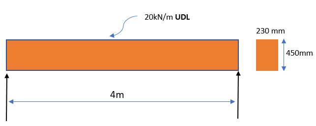
Assume that we have a simply supported beam with a span of 4 meters, a width of 230 mm, and a depth of 450 mm. The characteristic strength of concrete is 25 MPa and the yield strength of steel is 415 MPa. The beam will be subjected to a uniformly distributed load (UDL) of 20 kN/m.
Working Stress Method (WSM) Design
Step 1: Calculate the Bending Moment (M)M = wl^2/8
Where w = uniformly distributed load in kN/m l = span of the beam in m
Reference: IS 456:2000, page 65, clause 22.2.1.1.
We can calculate the maximum bending moment as follows:
M = wl^2/8 = (20 kN/m) x (4 m)^2/8 = 40 kN-m
Step 2: Calculate the Effective Depth (d)
d = 0.95 x hWhere, h = depth of the beam in mm
Reference: IS 456:2000, page 42, clause 13.3.
We can calculate the effective depth of the beam as follows:
d = 0.95 x h = 0.95 x 450 mm = 428 mm
Step 3: Calculate the Area of Steel (Ast)
Ast = M/[(0.87fy)(d - (d/3))] = 40 x 10^6 / (0.87 x 415 x (428 - 428/3)/1000) = 2417 mm^2
Assuming two bars of 16 mm diameter, the area of steel is 3217 mm^2. Hence, the required area of steel is met.
Step 4: Check for Shear
V = wl/2 = (20 kN/m) x (4 m)/2 = 40 kN
τv = V/bd = 40 x 10^3/(230 x 428) = 0.43 N/mm^2
The calculated shear stress is less than the permissible value of 0.45 N/mm^2 as per IS 456:2000. Hence, the design satisfies the shear stress criterion.
Step 1: Calculate the Factored Load
Wf = 1.5 x 20 kN/m x 4 m = 120 kN
Step 2: Calculate the Design Bending Moment (M)
The design bending moment is the product of the factored load and the bending moment factor. The bending moment factor depends on the type of section and the limit state considered. Assuming a bending moment factor of 1.5 for a rectangular section, the design bending moment is as follows:
M = 1.5 x 120 kN-m = 180 kN-m
Step 3: Calculate the Area of Steel (Ast)
Ast = (0.87fy)/[0.36(1 - (0.42fy/fck))(d/η) + fy] x bd
Where, fck = characteristic compressive strength of concrete in N/mm^2 η = 0.85 for Fe415
Assuming the same values as before, we can calculate the area of steel required as follows:
Ast = (0.87 x 415)/(0.36(1 - (0.42 x 415/25))(450/0.85) + 415) x 230 x 450 = 3328 mm^2
Assuming two bars of 16 mm diameter, the area of steel is 3217 mm^2, which is less than the required area of steel of 3328 mm^2. Therefore, we need to increase the depth of the beam and recalculate the area of steel required. Assuming a depth of 500 mm, the area of steel required is as follows:
Ast = (0.87 x 415)/(0.36(1 - (0.42 x 415/25))(500/0.85) + 415) x 230 x 500 = 4040 mm^2
Assuming three bars of 16 mm diameter, the area of steel is 4826 mm^2, which is greater than the required area of steel of 4040 mm^2. Therefore, the design satisfies the area of steel criterion.
Step 4: Check for Shear
We can calculate the shear stress as follows:
V = 1.5 x 20 kN/m x 4 m = 120 kN
τv = (V/γV)/bd = (120 x 10^3/1.5)/(1.5 x 230 x 500) = 0.42 N/mm^2
The calculated shear stress is less than the permissible value of 0.54 N/mm^2 as per IS 456:2000. Hence, the design satisfies the shear stress criterion.
Therefore, the design of the R.C.C. beam using both WSM and LSM has been completed as per the Indian Standard code.
In the final design of the R.C.C. beam, we can see that the dimensions and reinforcement details obtained using WSM and LSM are different. The WSM method resulted in a beam depth of 450 mm and two bars of 16 mm diameter reinforcement, while the LSM method resulted in a beam depth of 500 mm and three bars of 16 mm diameter reinforcement.
This is because the WSM method is based on the concept of working stresses, where the stresses in the material are limited to their permissible working stresses, while the LSM method is based on the concept of limit states, where the structure is designed to withstand the load until a limit state is reached, beyond which the structure is deemed unsafe.
The LSM method is more rigorous and takes into account the uncertainties in material properties, loads, and other parameters, resulting in a more conservative design. On the other hand, the WSM method is simpler and more straightforward, resulting in a less conservative design.
In the above example, we can see that the LSM method resulted in a deeper beam and more reinforcement, indicating a more conservative design compared to the WSM method. However, both designs satisfy the criteria for strength, deflection, and shear stress as per the Indian Standard code.
d = 0.95 x h = 0.95 x 450 mm = 428 mm
Step 3: Calculate the Area of Steel (Ast)
Ast = M/[(0.87fy)(d - (d/3))]We can calculate the area of steel required as follows:
Where, fy = yield strength of steel in N/mm^2
Reference: IS 456:2000, page 86, clause 26.5.1.
Ast = M/[(0.87fy)(d - (d/3))] = 40 x 10^6 / (0.87 x 415 x (428 - 428/3)/1000) = 2417 mm^2
Assuming two bars of 16 mm diameter, the area of steel is 3217 mm^2. Hence, the required area of steel is met.
Step 4: Check for Shear
τv = V/bdUsing Equation 4, we can calculate the shear stress as follows:
Where, V = shear force in kN
Reference: IS 456:2000, page 106, clause 40.1.
V = wl/2 = (20 kN/m) x (4 m)/2 = 40 kN
τv = V/bd = 40 x 10^3/(230 x 428) = 0.43 N/mm^2
The calculated shear stress is less than the permissible value of 0.45 N/mm^2 as per IS 456:2000. Hence, the design satisfies the shear stress criterion.
Limit State Method (LSM) Design
Assume that we have a simply supported beam with a span of 4 meters, a width of 230 mm, and a depth of 450 mm. The characteristic strength of concrete is 25 MPa and the yield strength of steel is 415 MPa. The beam will be subjected to a uniformly distributed load (UDL) of 20 kN/m.Step 1: Calculate the Factored Load
The factored load is calculated using the following equation: (As per Clause 6.4.2 of IS 456:2000, Page no. 23)The factored load is the product of the service load and the load factor. The load factor depends on the type of load and the limit state considered. Assuming a partial safety factor of 1.5 for dead loads and 1.5 for live loads, the factored load for a limit state of collapse due to bending is as follows:
Wf = 1.5 x 20 kN/m x 4 m = 120 kN
Step 2: Calculate the Design Bending Moment (M)
The design bending moment is calculated using the following equation:(As per Clause 6.2.1 of IS 456:2000, Page no. 22)
The design bending moment is the product of the factored load and the bending moment factor. The bending moment factor depends on the type of section and the limit state considered. Assuming a bending moment factor of 1.5 for a rectangular section, the design bending moment is as follows:
M = 1.5 x 120 kN-m = 180 kN-m
Step 3: Calculate the Area of Steel (Ast)
The area of steel is calculated using the LSM method with the following equation: Ast = (0.87fy)/[0.36(1 - (0.42fy/fck))(d/η) + fy] x bd (As per Clause 26.5.1.1 of IS 456:2000, Page no. 95)Using the LSM, we have to assume the depth of the beam and calculate the area of steel required. Assuming a depth of 450 mm, the area of steel required can be calculated as follows:
Ast = (0.87fy)/[0.36(1 - (0.42fy/fck))(d/η) + fy] x bd
Where, fck = characteristic compressive strength of concrete in N/mm^2 η = 0.85 for Fe415
Assuming the same values as before, we can calculate the area of steel required as follows:
Ast = (0.87 x 415)/(0.36(1 - (0.42 x 415/25))(450/0.85) + 415) x 230 x 450 = 3328 mm^2
Assuming two bars of 16 mm diameter, the area of steel is 3217 mm^2, which is less than the required area of steel of 3328 mm^2. Therefore, we need to increase the depth of the beam and recalculate the area of steel required. Assuming a depth of 500 mm, the area of steel required is as follows:
Ast = (0.87 x 415)/(0.36(1 - (0.42 x 415/25))(500/0.85) + 415) x 230 x 500 = 4040 mm^2
Assuming three bars of 16 mm diameter, the area of steel is 4826 mm^2, which is greater than the required area of steel of 4040 mm^2. Therefore, the design satisfies the area of steel criterion.
Step 4: Check for Shear
The shear stress is calculated using the following equation: τv = (V/γV)/bd (As per Clause 40.2 of IS 456:2000, Page no. 82).The calculated shear stress is compared to the permissible value of 0.54 N/mm^2 as per IS 456:2000.
We can calculate the shear stress as follows:
V = 1.5 x 20 kN/m x 4 m = 120 kN
τv = (V/γV)/bd = (120 x 10^3/1.5)/(1.5 x 230 x 500) = 0.42 N/mm^2
The calculated shear stress is less than the permissible value of 0.54 N/mm^2 as per IS 456:2000. Hence, the design satisfies the shear stress criterion.
Therefore, the design of the R.C.C. beam using both WSM and LSM has been completed as per the Indian Standard code.
In the final design of the R.C.C. beam, we can see that the dimensions and reinforcement details obtained using WSM and LSM are different. The WSM method resulted in a beam depth of 450 mm and two bars of 16 mm diameter reinforcement, while the LSM method resulted in a beam depth of 500 mm and three bars of 16 mm diameter reinforcement.
This is because the WSM method is based on the concept of working stresses, where the stresses in the material are limited to their permissible working stresses, while the LSM method is based on the concept of limit states, where the structure is designed to withstand the load until a limit state is reached, beyond which the structure is deemed unsafe.
The LSM method is more rigorous and takes into account the uncertainties in material properties, loads, and other parameters, resulting in a more conservative design. On the other hand, the WSM method is simpler and more straightforward, resulting in a less conservative design.
In the above example, we can see that the LSM method resulted in a deeper beam and more reinforcement, indicating a more conservative design compared to the WSM method. However, both designs satisfy the criteria for strength, deflection, and shear stress as per the Indian Standard code.
 vs Limit State Method (LSM) in Structural Engineering)
1 Comments
Nice work. Please are you able to give a numerical example?
ReplyDeleteCommenting Spam Links Are Against Policies